The objective of this project was to design a gearbox modelled after industrial-grade reduction gearboxes, with specific constraints to ensure practicality and feasibility. The design required a minimum speed reduction ratio of 12:1, fully 3D-printed components, both parallel and colinear outputs, and a kit format allowing for quick assembly without specialized tools. Collaborating with a team of three other students, we developed and 3D-printed the gearbox and created a set of detailed assembly instructions. These instructions allowed a third party to successfully assemble the gearbox in under 10 minutes, confirming the ease of construction. Following assembly, the gearbox was tested both manually and with an electric drill. The results exceeded expectations: the gearbox achieved the desired 14:1 ratio and withstood 10 seconds of drill operation, demonstrating our effective teamwork and robust design.
During our first team meeting, I took the initiative to help organize and guide the design process. I started by breaking the problem into a clearly defined objective and facilitating a team discussion to generate ideas. To foster collaboration, I set up an online drawing board for team members to visually present and explain their suggestions. After evaluating the proposed ideas, we identified the most feasible options and outlined a task list for implementation, which we divided evenly among the team. My primary contribution was performing calculations for the gear ratios—determining dimensions, number of teeth, and creating CAD designs—to ensure the gearbox achieved the desired speed reduction.
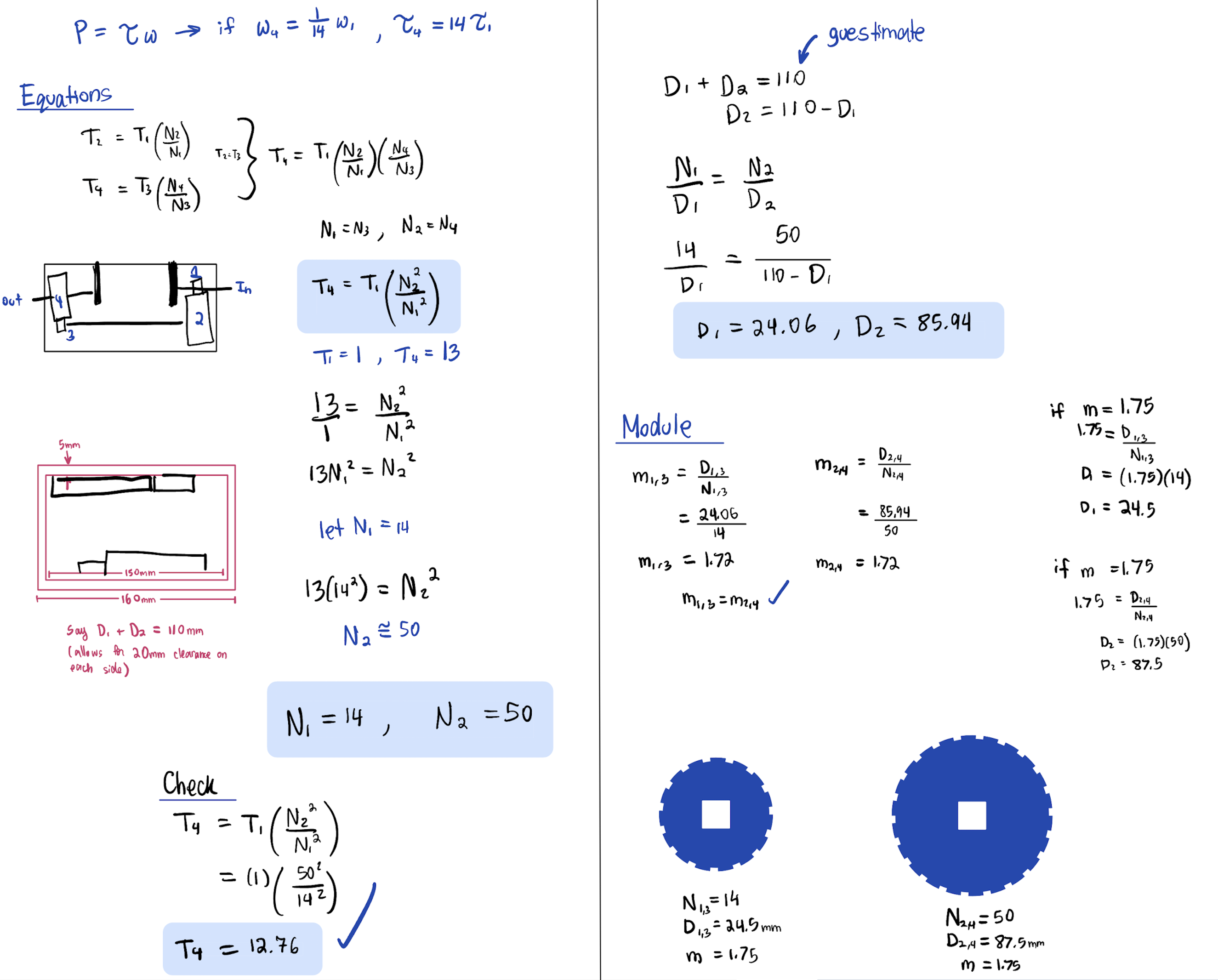
The figure below shows an early iteration of the calculations I performed to determine the necessary pitch diameter and number of teeth to obtain the desired speed reduction ratio.
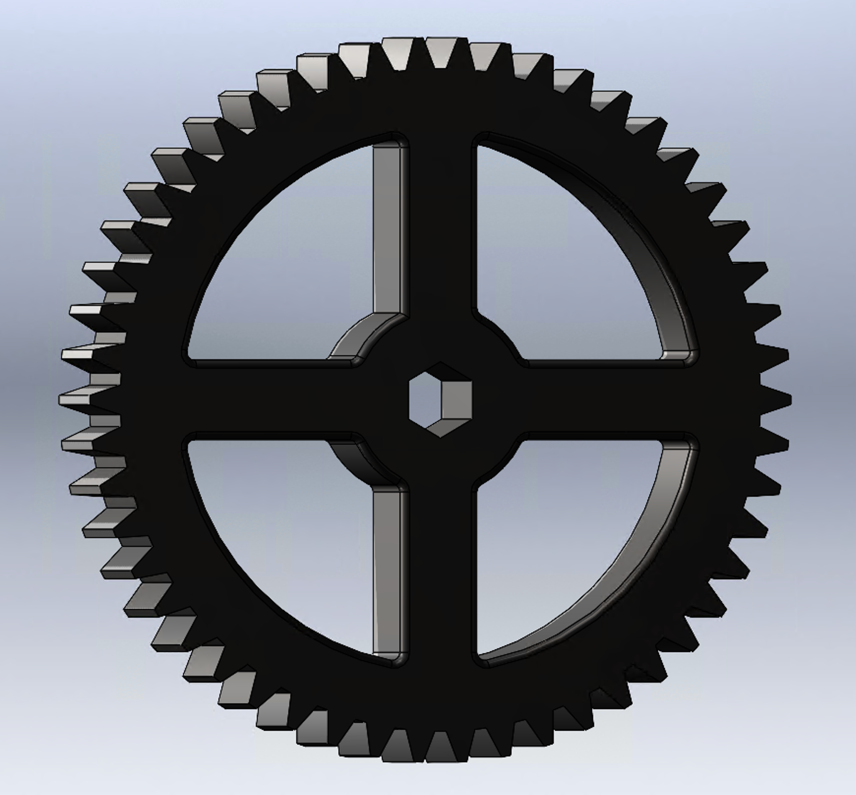
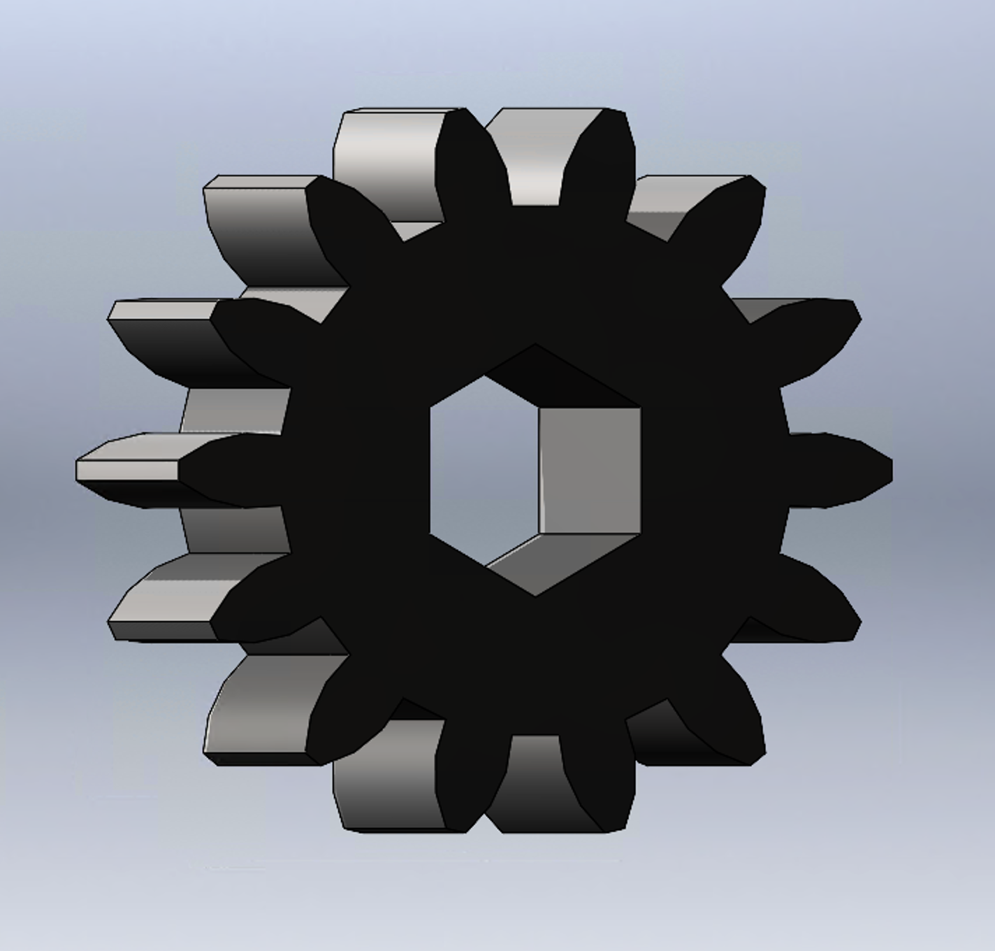
The figures below display CAD models of the two gears. The pitch diameter and number of teeth were slightly adjusted from the original calculations to better integrate with the surrounding components. The gears feature a hexagonal center, allowing them to lock onto the hexagonal shaft and prevent rotational slipping.
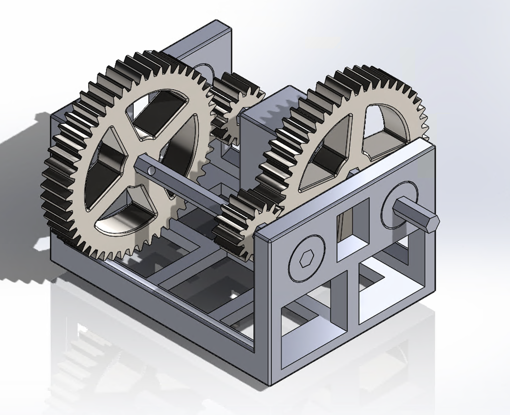
The figure below shows the complete CAD model of the final design, which was 3D-printed and tested.
While the design was successful, several challenges were encountered during the design and testing process. Although we were limited to two iterations (one prototype and one final design), there are several ways to improve the design's performance and effectiveness. Below is a list of challenges and proposed solutions:
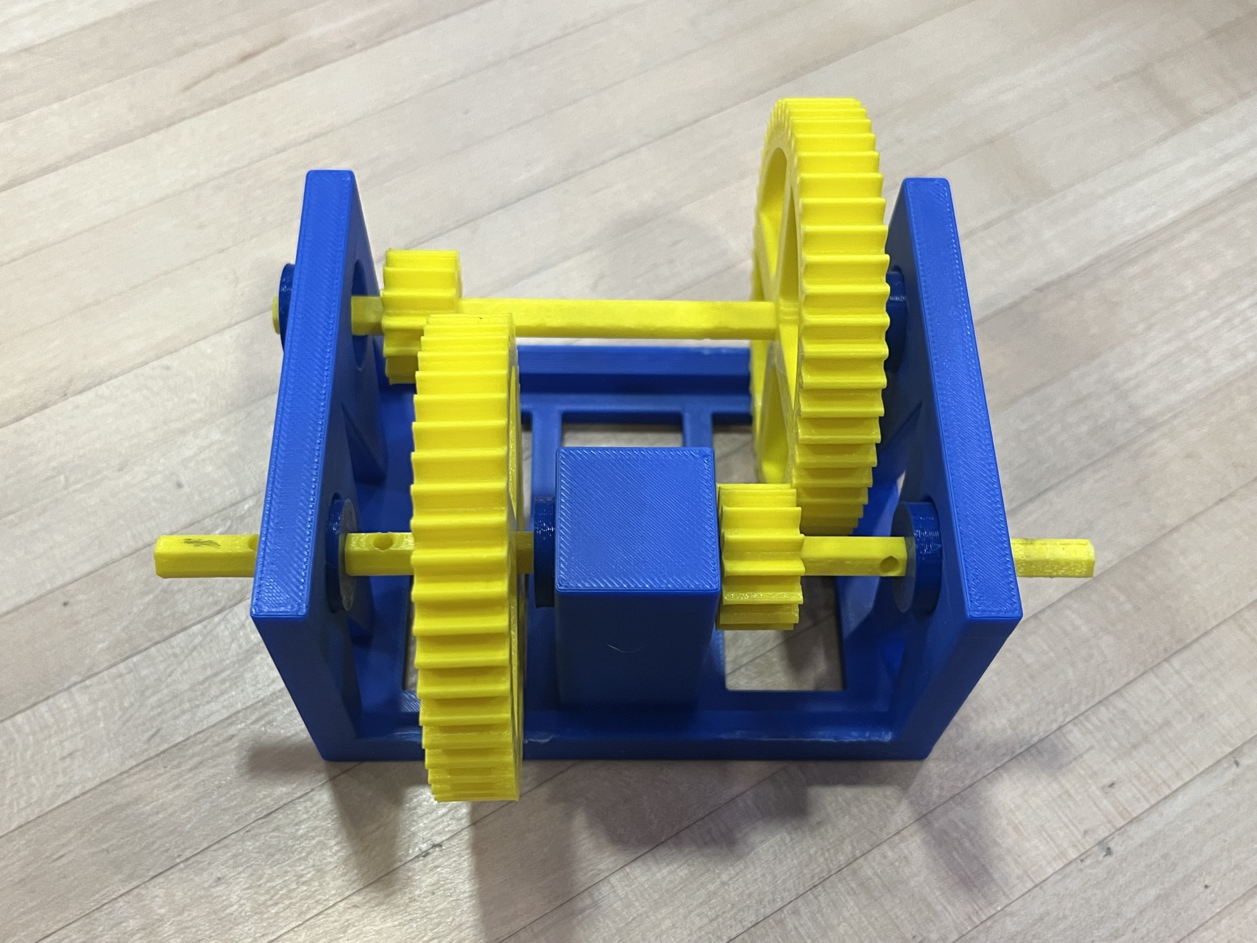
This caused the gearbox to fail during the drill test, as the gears became misaligned and prevented motion transmission. Originally, we planned to place small pins on either side of each gear to maintain proper alignment (holes can be seen in the shaft where the pins were intended to be placed). However, due to 3D printing issues and time constraints, we were unable to implement this feature. If we were to print this design again, we would add the pins to ensure the gears remain aligned throughout operation.
Our final design included press-fit bushings on the hexagonal shafts, allowing smooth rotation within the housing. Although we briefly discussed adding pins to maintain alignment within the housing, we decided to prototype without pins. Unfortunately, due to printing delays, we realized the pins’ necessity too late and could not implement this solution in time. As a result, we had to hold the bushings during the drill test.
For future improvements, there are two options:
The image below shows the final 3D-printed product, captured immediately after testing. The misalignment of the gears is a result of shifting during rotation, as discussed earlier.
This was my first experience creating a working model from a conceptual design. While I was aware of the importance of conceptual iteration, this project highlighted the necessity of iterative improvement following prototyping. I learned that even the best initial design will require adjustments to address unforeseen issues. This experience emphasized the need to plan for the unknown and to balance trade-offs between features and performance, especially under time or resource constraints. Overall, this project boosted my confidence in my design abilities, as I successfully contributed to creating and building a functional model for the first time.