Throughout this two-day machining course, I learned how to operate a lathe, mill, and drill press. Through hands-on training, I practiced interpreting engineering drawings and using measurement tools to create components that met the provided specifications. We were given raw materials which we then had to measure, mark, cut, machine, and file to produce parts that were compatible with one another. Once each part was manufactured according to the specifications, we assembled the components using instructions provided in the course workbook. The final product – a mini pneumatic engine – was assembled and successfully tested using compressed air, demonstrating the importance of precision and attention to detail in the manufacturing process.
The steps below provide an overview of the manufacturing process I followed to machine the cylinder.
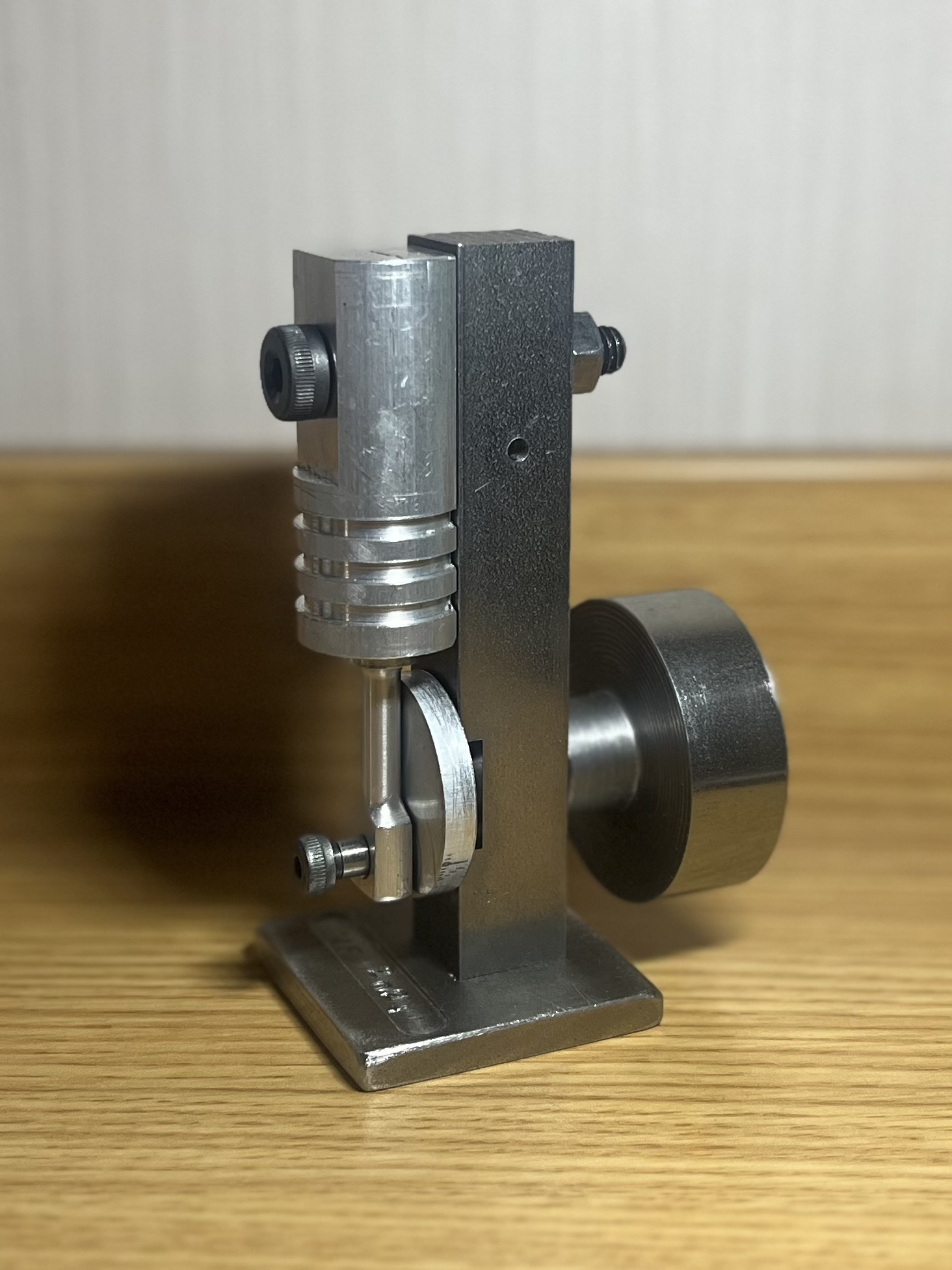
The figure below shows the final assembled pneumatic engine. Following assembly, the engine was tested using compressed air. The engine operated smoothly throughout testing, with all components remaining securely in place, demonstrating the effectiveness of the precision machining and assembly process.
It was fascinating to see how concepts from my classes apply in real-world settings, even in areas unrelated to machining. For example, in my materials science course, I learned how the microstructure of steel changes with carbon content, affecting its hardness and brittleness. In the machining course, I discovered how these material properties impact spindle speeds and tool selection, such as using specific mill bits for high-carbon steel. Making these connections helped me better understand the reasoning behind both theory and practice.
This course gave me a deeper appreciation for engineering drawings from the perspective of a machinist. In my design course, I learned how to create engineering specifications and drawings, as well as how to draft them in SolidWorks. In the machining course, I shifted from creating drawings to interpreting them, ensuring the parts I machined met exact specifications. Seeing both sides of the process—design and manufacturing—has made me more confident in understanding and applying engineering principles.